
Thermoplastic Lined Tubing Recommended Practice Care and Handling
Document information: October 21, 2016 RP7.55.1, Revision 2.0 Recommended Practice Thermoplastic Lined (TPL) Tubing with API 8 Round Connections
1.0 Scope
1.1 This document sets forth the recommended practice for the field running and handling procedures that should be utilized in conjunction with Western Falcon Incorporated (WFI) and Polycore Tubular Linings Corporation (PTL) Thermoplastic Lined Tubing.
2.0 References
2.1 The following documents were used for reference in the preparation of this document and should be followed unless otherwise specified:
2.1.1 API Recommended Practice 5C 1 2.1.2 API Bulletin 5A2
3.0 Equipment
3.1 The following list of equipment should be on location when WFI/PTL Thermoplastic Lined Tubing is run:
3.1.1 Ample supply of thread compound.
NOTE: Western Falcon does not recommend use of a bottlebrush for thread lubricant application. If a bottlebrush must be utilized, care must be taken to evenly spread thread lubricant around the entire surface of the pin and box thread.
3.1.2 Appropriate Product Data Sheet
3.1.3 Drift Assembly
3.1.4 Stabbing guide required for cold weather handling.
4.0 Field Running and Handling Procedures
4.1 Precautions
4.1 Precautions
4.1.1 Consult appropriate product data sheet to ensure well conditions are within allowable limits of the thermoplastic liner being installed.
4.1.2 Consult appropriate product data sheet for the dimensions of thermoplastic liners before running tools or equipment. Pumps, rod boxes, and any other downhole equipment should be inspected and free of sharp edges, excess corrosion, or other abnormalities that could shave plastic.
4.1.3 Thread protectors should always remain in place when moving or handling tubulars.
4.1.4 Do not use a high temperature heating device or welding torch to remove thread protectors.
4.1.5 Avoid rough handling. Do not unload the pipe by dropping.
4.1.6 Never use end hooks inside the end of pipe. Handle with slings only.
4.1.7 Cold Weather Handling. When moving, installing or pulling Enertube™ or Ultratube™ lined tubulars at temperatures below 5°C (41°F), the following special procedures must be implemented to avoid significant shock or impact loads against the liner or pipe body that can fracture the liner in cold conditions. Cold temperatures increase the vulnerability of the liner to impact damage and its sensitivity to suddenly applied stress.
a.) A trained Field Service Technician is recommended during installation of tubing lined with these products
b.) Tubulars lined with either Enertube or Ultratube should always be stripped between each layer and have heavy-duty protectors on every pin end. For Range 2 tubing there should be a minimum of three strips per layer with four strips being preferred. All layers should be stripped with the strips in each layer being vertically aligned with the strips in all other layers.
c.) Do NOT drop pipe or allow pipe to free fall off of trucks, lifts, or racks both at the storage yard and on location. Experienced operators should be used to minimize the banging together of joints while being picked up, released, or during movement. At fixed locations the use of specialized equipment may be warranted.
d.) Do NOT strike or side impact the tubing with handling equipment, tools, or other objects.
e.) Do NOT drag tubing where it can bounce and cause impact damage.
f.) Heavy-duty pin end protectors are to remain on lined tubing at all times and during all phases of handling and storage. The protectors should be removed as the last step immediately prior to stabbing the connection into the collar and reinstalled as the first step immediately after breaking the connection during pulling.
g.) Plastic stabbing guides are required during installation.
h.) Minimum API torque should be used during make-up of tubulars at all times. Back up on the tubing and mark the coupling and pipe with a chalk or paint stick. Verify that coupling does not rotate relative to the joint it was originally installed on during make-up. If the minimum torque is to be exceeded during make-up, WFI/PTL would recommend the use of extended length couplings. Optimal torque must not be exceeded during make-up with extended length couplings.
i.) Hydrostatic testing prior to running the lined pipe into the well is not recommended for Enertube or Ultratube at temperatures below 5°C (41°F).
j.) The Field Service Technician will make the determination if the conditions worsen to the point that it is no longer advised to continue handling the lined tubing.
4.2 Preparation
4.2 Preparation
4.2.1 By visual inspection, ensure that all necessary running equipment and accessories (subs, crossovers, nipples, hangers, pup joints, etc) are available and in good condition.
NOTE: Following visual inspection of the running and accessory equipment, discuss field running procedures with the Rig Supervisor.
4.2.2 Slip type elevators must be utilized for special clearance / slim hole coupling applications.
4.2.3 All WFI/PTL lined pipe shipped from lining plants will have protectors installed and thread compound applied (Ultratube will have Artic thread compound applied).
4.2.4 Lined pipe shipping from WFI/PTL plants will have had couplings bucked on to API specified torque and standoff verified.
4.2.5 If field thread inspection is required, be certain that thread compound and protectors are reapplied.
4.2.6 Do NOT remove pin end thread protectors until joint is hanging in the derrick. Moving unprotected pin threads can result in liner damage as well as pin thread damage.
4.2.7 Do NOT use hooks or any other device inserted into the coupling or end of the pipe for material handling as this could result in damaged liner and pipe.
4.3 Running Thermoplastic Lined Tubulars into the Well
4.3 Running Thermoplastic Lined Tubulars into the Well
4.3.1 Stabbing guides are not required but can be used at Operator’s request.
NOTE: This applies unless weather conditions during installation qualify as “Cold Weather Handling (Section 4.1.7)”.
4.3.2 WFI/PTL recommends that all thermoplastic lined pipe be made-up to API minimum torque (see Minimum Torque Table for standard length couplings in Appendix A). If minimum torque is to be exceeded during make-up, WFI/PTL would recommend the use of extended length couplings and not to exceed optimal torque during make-up. (See Optimum Torque Table for extended length couplings in Appendix A) Over-torqueing the connection can damage both threads and liner.
4.3.3 When properly calibrated torque gauges reading in foot-pounds are not available, apply back-ups to tube body below the coupling and make-up the connection without significantly turning the coupling. This can be monitored by marking a vertical line with a chalk stick down the coupling and onto the tube; after make-up is complete check to see that the line remains unbroken. Lower this joint down in the well. Then lower the drift down through the connection to check make-up (see Appendix C).
4.3.4 Note:The method in Section 4.3.3 is only applicable when running a string of API threaded and coupled thermoplastic lined tubing the very first time into a well as the make-up at the plant can be verified to be done properly only that first time.
4.3.5 Do NOT make-up past the last scratch of the pin thread.
4.3.6 After following this procedure for 10 or more joints, the tongs should be set and regular installation can proceed (drifting each connection). Once the tongs are set begin recheck every tenth joint for coupling movement upon make-up.
4.3.7 All downhole pipe should be drifted during installation (see Appendix C for drift procedure). Steel drifts of the proper size are acceptable (see Appendix B for drift dimensions).
4.3.8 Dropping a rabbit through the pipe as it is being picked up is NOT a suitable substitute for downhole drifting. If a rabbit is used WFI/PTL suggests only with the Polycore™ HDPE lining. The other higher temperature liners can be damaged with rabbit style drifting.
4.4 Operation
4.4 Operation
4.4.1 No Rod Guides. It is not necessary, nor recommended, to use rod guides. Most rod guides will damage the liner.
4.4.2 The use of “top hold down pumps” is recommended in highly deviated wells.
4.4.3 Pumps, rod boxes, and any other downhole equipment should be inspected and free of sharp edges, excess corrosion, or other abnormalities that could shave plastic.
a.) It might be necessary to bevel the bottom of the pump if the lower edge seems sharp
b.) Sharp edges or corrosion on the rod boxes can shave the liner, jeopardizing its integrity.
c.) Rods and downhole equipment can be inspected with a clean dry cotton cloth rubbed over them looking for snags.
4.4.4 Coiled tubing or wirelines can be run inside WFI/PTL liners. First check the leading edge for sharp edges and burrs using the cotton cloth.
4.4.5 Hot Oiling or Hot Water Flushes. Use caution not to exceed the temperature limits of the liner (consult Product Data Sheet). Higher temperature resistant liners can be installed in the appropriate areas of the string to accommodate wells that require hot liquid treatments.
4.4.6 Swabbing WFI/PTL lined tubing is recommended using rubber cups (not wire cups) and keeping the line speed as slow as possible to accomplish the job.
4.4.7 Hydrostatic Testing or pressure testing is common practice with thermoplastic liners to proof check the pipe connection for leaks and structural integrity. The preferred method would be full string testing. The pressure test duration could take up to 1 hour to obtain a stabilized test pressure when testing the full string. In some cases, the thermoplastic liner can stretch slightly during pressure testing. However, if testing as the pipe is inserted into the well is required:
a.) Notify the testing company that WFI/PTL thermoplastic liner has been installed in the pipe. This will allow them to insure the proper sized cups will be on site.
b.) Hydrostatic testing is acceptable to API Standards of the pipe.
c.) WFI/PTL requires the use of a two line set of test bars. This will allow separate pressure lines for cuff inflation and annulus pressurization. The use of single line test bars will likely damage the liner and is not recommended.
d.) Pulling the test bar with the cups partially engaged will result in liner damage.
e.) In cold weather, do NOT hydrostatic test tubulars lined with Enertube or Ultratube prior to running into the well (see Section 4.1.7 Cold Weather Handling.)
4.5 Pulling Pipe and Standing Back
4.5 Pulling Pipe and Standing Back
4.5.1 If it is necessary to remove the pipe from the well and stand back in the derrick, installing pin protectors before standing back is the preferred method to protect the liner and pin threads. Proper protection of pin ends is required before standing back.
4.5.2 Best Practice is to always install pin protectors if the pipe is to be laid down.
4.5.3 WFI/PTL recommends referring to Section 4.3, adhering to API minimum torque, and drifting all connections after make-up when reinstalling pipe into the well.
Helpful Items Available from WFI/PTL Include:
- Field Service Technician
- Replacement and Cross-Over Couplings (with IPC applied)
- Drift Kits
- Stabbing Guides (polyurethane)
- Thermoplastic Lined Pup Joints (individual or sets)
Appendix A
WFI/PTL Minimum Make-Up Torques for Standard Length Couplings
- API Minimum Torque {API RP 5C1 (R2010)}
- All torque values are given in foot-pounds.
| API Tubing | J-55 | L-80 | N-80 | |
|---|---|---|---|---|
| 2-3/8″ 4.60/4.70 lb/ft (60.3 mm 6.85/6.99 kg/m) | NUE | 550 | 740 | 770 |
| 2-3/8″ 4.60/4.70 lb/ft (60.3 mm 6.85/6.99 kg/m) | EUE | 970 | 1,320 | 1,350 |
| 2-7/8″ 6.40/6.50lb/ft (73.0 mm 9.52/9.67kg/m) | NUE | 790 | 1,070 | 1,100 |
| 2-7/8″ 6.40/6.50lb/ft (73.0 mm 9.52/9.67kg/m) | EUE | 1,240 | 1,690 | 1,730 |
| 3-1/2″ 9.20/9.30 lb/ft (88.9 mm 13.69/13.84kg/m) | NUE | 1,110 | 1,520 | 1,550 |
| 2-7/8″ 9.20/9.30 lb/ft (88.9 mm 13.69/13.84kg/m) | EUE | 1,710 | 2,350 | 2,400 |
| 4-1/2″ 12.60/12.75 lb/ft (114.3 mm 18.75/18.97kg/m) | NUE | 1,310 | 1,800 | 1,830 |
| 4-1/2″ 12.60/12.75 lb/ft (114.3 mm 18.75/18.97kg/m) | EUE | 2,150 | 3,020 | 2,960 |
| API Casing | J-55 | |
| 4-1/2″ 10.50 lb/ft (114.3 mm 15.63kg/m) | STC | 990 |
| 4-1/2″ 11.60 lb/ft (114.3 mm 17.26kg/m ) | LTC | 1,220 |
| 5-1/2″ 14.00lb/ft (139.7 mm 20.83kg/m) | STC | 1,290 |
| 5-1/2″ 15.50 lb/ft (139.7 mm 23.07kg/m) | LTC | 1,630 |
| 5-1/2″ 17.00lb/ft (139.7 mm 25.30kg/m) | LTC | 1,850 |
WFI/PTL Optimum Torques for Extended Length Couplings
- API Optimum Torque {API RP 5C1 (R2010)}
- All torque values are given in foot-pounds.
| API Tubing (Optimum Torque) | J-55 | L-80 | N-80 | |
| 2-3/8″ 4.60/4.70 lb/ft (60.3 mm 6.85/6.99 kg/m) | NUE | 730 | 990 | 1,020 |
| 2-3/8″ 4.60/4.70 lb/ft (60.3 mm 6.85/6.99 kg/m) | EUE | 1,290 | 1,760 | 1,800 |
| 2-7/8″ 6.40/6.50lb/ft (73.0 mm 9.52/9.67kg/m) | NUE | 1,050 | 1,430 | 1,470 |
| 2-7/8″ 6.40/6.50lb/ft (73.0 mm 9.52/9.67kg/m) | EUE | 1,650 | 2,250 | 2,300 |
| 3-1/2″ 9.20/9.30 lb/ft (88.9 mm 13.69/13.84kg/m) | NUE | 1,480 | 2,030 | 2,070 |
| 3-1/2″ 9.20/9.30 lb/ft (88.9 mm 13.69/13.84kg/m) | EUE | 2,280 | 3,130 | 3,200 |
| 4-1/2″ 12.60/12.75 lb/ft (114.3 mm 18.75/18.97kg/m) | NUE | 1,740 | 2,400 | 2,440 |
| 4-1/2″ 12.60/12.75 lb/ft (114.3 mm 18.75/18.97kg/m) | EUE | 2,860 | 3,940 | 4,020 |
Appendix B
WFI/PTL Thermoplastic Lined Tubing Drift Diameters
| Polycore™ Ultratube™ Extremetube™ | Inches | Millimeters |
| 2-3/8″ 4.60/4.70 lb/ft (60.3 mm 6.85/6.99 kg/m) | 1.60 | 40.6 |
| 2-7/8″ 6.40/6.501b/ft (73.0 mm 9.52/9.67 kg/m) | 2.00 | 50.8 |
| 3-1/2″ 9.20/9.30 lb/ ft (88.9 mm 13.69/13.84kg/m) | 2.50 | 63.5 |
| 4-1/2″ 12.60/12.75 lb/ft (114.3 mm 18.75/18.97kg/m) | 3.40 | 86.4 |
| Modified Polycore™ Enertube™ | Inches | Millimeters |
| 2-3/8″ 4.60/4.70 lb/ft (60.3 mm 6.85/6.99 kg/m) | 1.516 | 38.5 |
| 2-7/8″ 6.40/6.501b/ft (73.0 mm 9.52/9.67 kg/m) | 1.901 | 48.3 |
| 3-1/2″ 9.20/9.30 lb/ ft (88.9 mm 13.69/13.84kg/m) | 2.347 | 59.6 |
| 4-1/2″ 12.60/12.75 lb/ft (114.3 mm 18.75/18.97kg/m) | 3.215 | 81.7 |
Appendix C
WFI/PTL Drifting Procedure for Thermoplastic Lined Tubulars
Inspect rope for tears, frays, and damage. SECURELY attach rope to eye on drift.
1. Tie a knot in the rope at a distance approximately six feet longer than the longest joint (or stand) in the tubing string away from the drift. This knot will act as a “stop” to keep the line from falling through the pulley into the wellbore and as a reference point to verify that the drift has cleared through the connection.
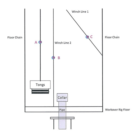
2. Tie off the pulley at one of three locations (tong chain – Point A; on the winch line after you secure it to the rig floor – Point B; or the winch line after you secure it to the floor chain – Point C). See sketch below.
3. Run rope with the drift tied on the end through the pulley. Hold onto the drift line and secure it on rig floor to keep line from falling into wellbore. Drop drift into tubing below rig floor and store coiled drift line on rig floor.
4. When drifting the first joint, be careful and check for nipples, swages or other attachments that the drift will not pass through.
5. In the event that the drift gets stuck, tie off the rope on the elevators, pull up the joint or stand, then breakout that connection and pull the drift out through the bottom of the joint.
See Appendix B for Drift Diameters.
NOTE: Tubing can be drifted in singles or doubles (stands). Set location of knot on rope accordingly.
Appendix C
WFI/PTL Drifting Procedure for Thermoplastic Lined Tubulars
Inspect rope for tears, frays, and damage. SECURELY attach rope to eye on drift.
1. Tie a knot in the rope at a distance approximately six feet longer than the longest joint (or stand) in the tubing string away from the drift. This knot will act as a “stop” to keep the line from falling through the pulley into the wellbore and as a reference point to verify that the drift has cleared through the connection.
2. Tie off the pulley at one of three locations (tong chain – Point A; on the winch line after you secure it to the rig floor – Point B; or the winch line after you secure it to the floor chain – Point C). See sketch below.
3. Run rope with the drift tied on the end through the pulley. Hold onto the drift line and secure it on rig floor to keep line from falling into wellbore. Drop drift into tubing below rig floor and store coiled drift line on rig floor.
4. When drifting the first joint, be careful and check for nipples, swages or other attachments that the drift will not pass through.
5. In the event that the drift gets stuck, tie off the rope on the elevators, pull up the joint or stand, then breakout that connection and pull the drift out through the bottom of the joint.
See Appendix B for Drift Diameters.
NOTE: Tubing can be drifted in singles or doubles (stands). Set location of knot on rope accordingly.
Contact your Field Representative Today for a Customized Solution
Western Falcon has demonstrated success in over 70 million feet (20 million meters) of pipe in the last 20 years! There is not a well we can’t fix.